VectorEZ helps you quickly convert a bitmap image to a vector format.
The example below will guide you through the process of loading an image,
selecting a color in that image, extracting the contours around the specified color, tuning the result,
and finally saving it in a vector graphics format (SVG).
1. Load a bitmap image
Use the menu File → Open image... to open a bitmap file. Alternatively, the user can drag and drop the image file directy onto the viewport area. The supported image formats are: BMP, JPEG, PNG, TGA and TIFF. In this example we open a scanned image, bird.png.
2. Select the segmentation color
Use the pipette tool in the "Source image" panel to select the color that will be used to extract the contour.
3. Tune the vectorization
In the "Vectorization" panel, use the "Precision" slider to tune the result to your convenience. Moving the slider to left will lessen the precision,
meaning the curve will fit more loosely to the input image, the contour will be less detailed and the resulting file will be smaller. On the contrary,
moving the slider to the right will result in a more detailed curve that fits more closely to the input. The output file will be larger.
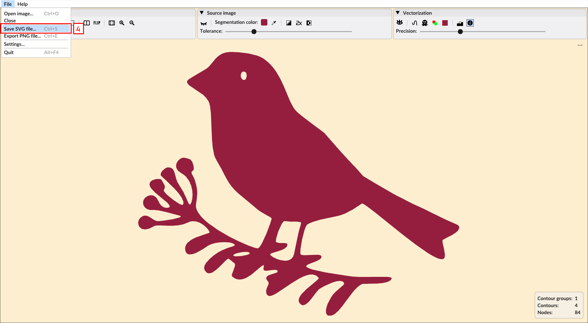
4. Save the result
Save the result as a SVG file once you are satisfied with the vectorization output.
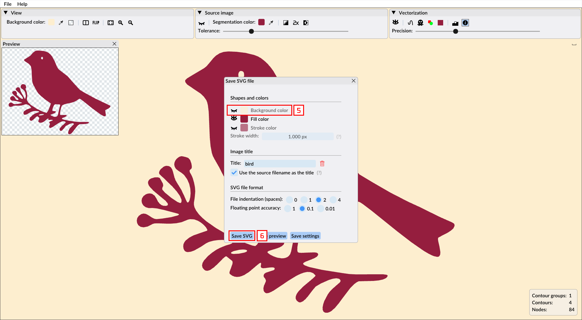
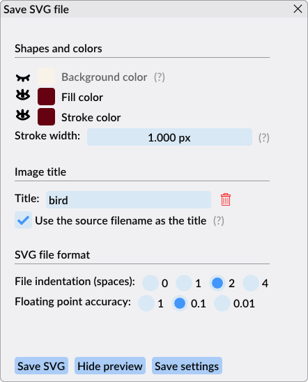
The menu option opens a preview window of the vectorization as it will be saved in SVG. The user is free to tune the image before it is saved. Usually, one
prefers to save the silhouette with a transparent background. Click on the eye icon next to the background color to ensure it is hidden. Finally, click the
"Save SVG" button to select a file and commit the result!
As a result of this tutorial we saved the file bird.svg.
We hope this walkthrough gave you a good enough overview of what VectorEZ has to offer!
In the next sections we will provide a more detailled documentation of the tool functionalities.
Warning
The demo version of the application does not the allow the user to save the result in a vector format (i.e. SVG).
The user can however still export the vectorization to PNG.
Purchase the full version of VectorEZ to save the vectorization result as a SVG file.
Controls and key bindings
Action
Windows
macOS
Pan
Right mouse button + drag
Touchpad
Zoom in/out
Mouse wheel
Touchpad
Zoom in
+ ; PageUp
+ ; PageUp ; ⌘ + =
Zoom out
- ; PageDown
- ; PageDown ; ⌘ + -
Zoom to fit
0 ; Ctrl + 0
0 ; ⌘ + 0
Zoom box
Left mouse button
Mouse button
Split view
S
S
Flip view
F
F
Open image
Ctrl + O
⌘ + O
Save as SVG
Ctrl + S
⌘ + S
Quit application
Alt + F4
⌘ + Q
Interface
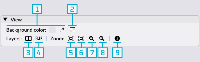
The View panel
The view panel gives the user control on what is displayed in the viewport. It does not affect the vectorization process.
Set the viewport's background color with a color editor or a pipette tool.
Checkerboard: Replace the background color by the checkerboard pattern.
Split view (shortcut: S): Show the source image layer on the lefthand side of the viewport and the vectorization one on the righthand side.
Flip view (shortcut: F): Flip between the source image and the vectorization layers in the viewport.
Zoom to actual size: Display the source image at its original size. (Zoom: 100%.)
Zoom to fit: Reset the zoom of the image to fit the viewport.
Zoom in. Also with the mouse wheel (Windows) or the touchpad (macOS), and the shortcut keys.
Zoom out. Same as above.
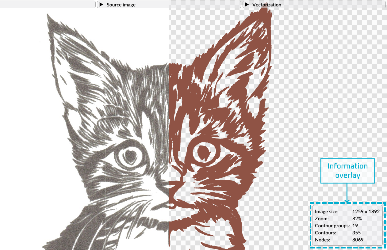
Hide/show the view information in the information overlay, located at the bottom righthand corner of the viewport.
The background color does not affect the vectorization, it can however be saved as the background color of the vector image file, depending on its format.
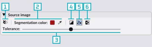
The Source Image panel
The source image panel controls what pre-processing is applied to the source image, and which color is used to extract the silhouettes to be vectorized.
Hide/show the source image.
Set the segmentation color with a color editor or a pipette tool.
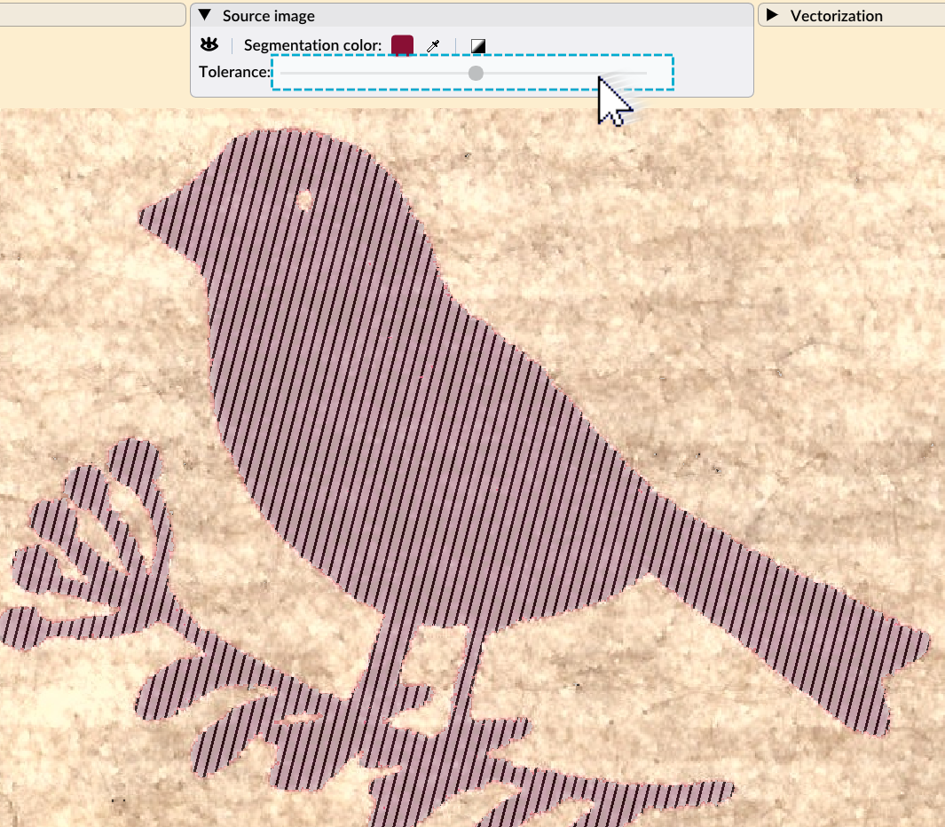
(Slider) Set the tolerance on the segmentation color.
Filter the source image and convert it to a monochrome image.
Upscale the source image to catch finer details.
Invert the color selection.
The segmentation color is the color used the define the silhouette shapes that must be vectorized. In the output file, it is also used as the fill color of the vector paths.
The upscale tool will scale the image resolution two times. This is helpful if the image has small details that you want to keep in the image trace. It usually leads to a better
quality result, and therefore it is enabled automatically on small resolution images (< 1k). On higher resolution images it is disabled by default and it is up to the user
to enable it or not. The upscaling will impact the speed of the vectorization. Also, if you are vectorizing from a very high quality input (for instance, a 600dpi scanned image),
it is likely that the upscale feature won't impact the result significantly.
Monochrome images
With monochrome images, the grayscale button [4] is toggled automatically. This does not affect the result of the segmentation and the vectorization, only the processing time.
While the mouse hovers on the tolerance slider [3], the silhouette is highlighted in the source image
Hover the mouse on the tolerance slider to highlight the color selection
Warning
The highlighting is only visible if the source image is displayed.
The Vectorization panel
Finally, the vectorization panel controls the transformation process of the selected silhouette to the vector paths.
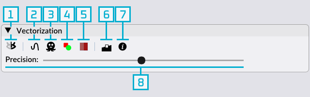
Hide/show the vectorization layer in the viewport.
Sharp corners and straight segments: When selected, allow sharp angles at anchor nodes and also enable the detection of straight segments. When unselected (the default), all nodes are smooth.
Silhouette only: When selected, keep only the outer contour of every shape of the image in the vectoriezation.
Control the style of the vector paths displayed in the viewport: filled or not, outlined or not.
Open the vectorization color selection window, allowing the user to control the colors of the vector paths.
Hide/show the anchor nodes. Those are the extremities of the Bezier curves that form the contour paths.
Hide/show the information regarding the current vectorization in the information overlay, located at the bottom righthand corner of the viewport.
(Slider) Set the precision of the vectorization. It decides how closely the vector contours will fit to the silhouettes extracted around the segmentation color. The higher the precision, the more accurate the fit, and the higher the number of nodes.
Impact of the precision slider on the output size
In many use-cases, one may prefer to reduce the number of nodes, in order to reduce the complexity of the output vectorization, as well as its size.
This is where the real-time rendering of VectorEZ truly shines!
By immediately witnessing the impact the precision has on the vectorization, the user can quickly find a good compromise between accuracy, aesthetic and output size.
The color selection window
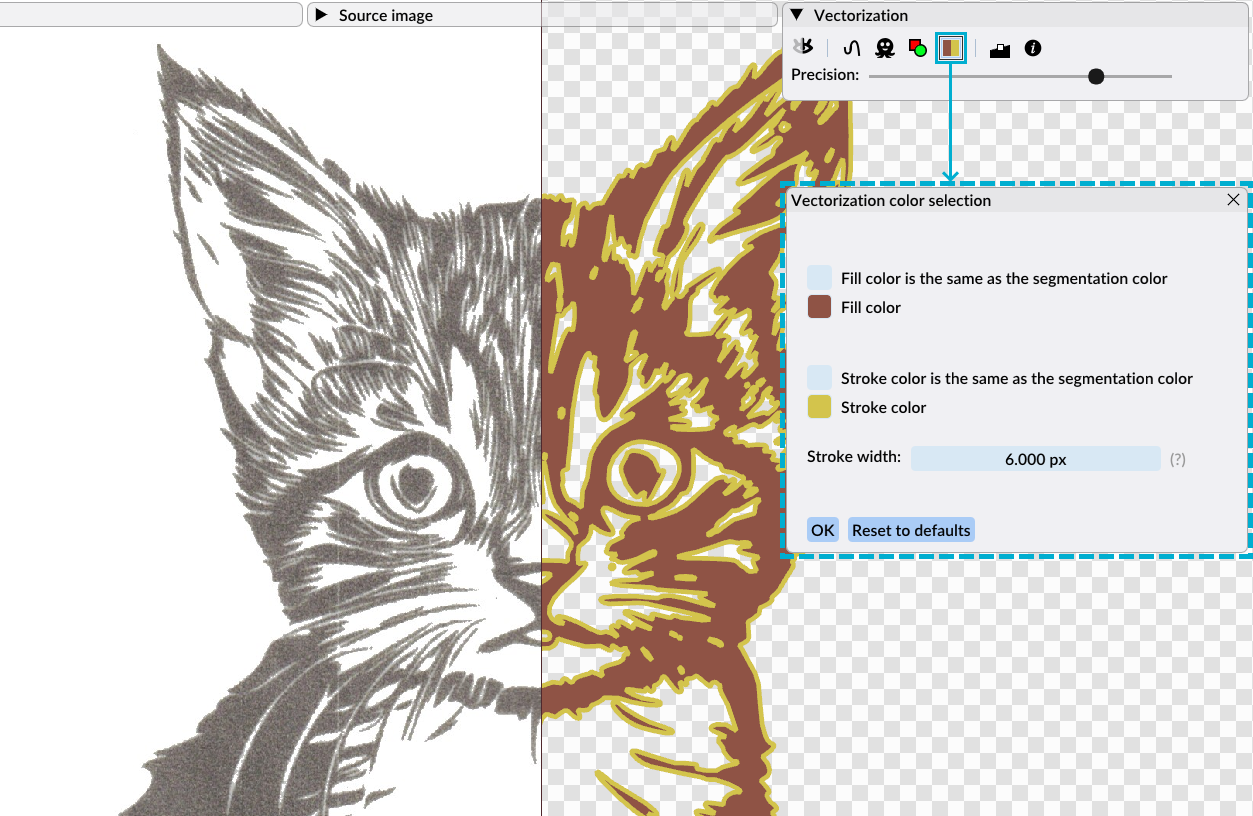
Accessible with the button [5] of the vectorization panel, the color selection window allows the user to customize the path and fill colors of the vector image.
The thickness of the vector paths (i.e., the stroke width) can also be modified here.
When exporting the vector graphics as PNG or SVG files, those visual settings will be used as the default for the final result.
The vectorization color selection window is accessible via the vectorization panel
The information overlay
Located in the bottom righthand corner of the viewport, the overlay displays extra information regarding the source image and its vectorization. The user can enable or disable the
information shown in the overlay using the information buttons in the view and vectorization panels.
Exporting the result
When the user is satisfied with the vectorization result, she can export the result in various formats:
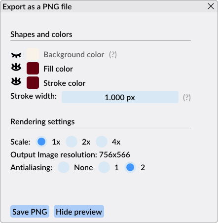
Export to PNG: Available in the demo and the full versions of VectorEZ, it will produce a rendering of the vector graphics, with a transparent background or not, and save it in the PNG format.
Save as SVG: Only available in the full application, it saves the exact definitions of the vectorization in a vector image format.
Before exporting/saving the result, the user is invited to fine tune the style of the output (color, stroke width, etc.) and to set some properties specific to the output file format.
A preview of the result can also be displayed.
Below are the screenshots of the options available for each format: